MESI
Die Website wird ausschließlich auf Englisch angeboten.
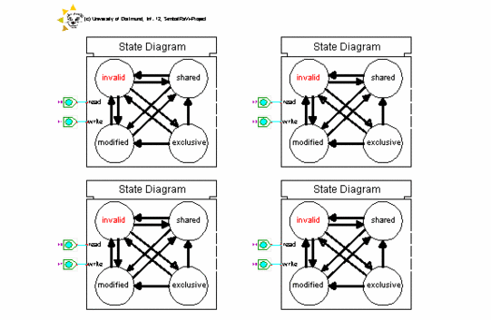
The component "mesi" explains the dynamic behaviour of the MESI protocol within a multi-processor system by visualizing the cache state transitions. Depending on read and write requests of the different processors, the component shows the state transitions of the corresponding cache lines.
The MESI (Modified-Exclusive-Shared-Invalid) protocol is an example for a write-invalidate cache coherency protocol. The underlying protocol flow of the component is based on the description in the books "Computer Organization & Design, The Hardware/Software Interface " by Hennessy & Patterson (chapter 9) and "Computer Organization and Architecture" by William Stallings (chapter 16.3). For more details about the cache state transitions, please have a look at the entire state-transition diagram of the component. A visualization of the data and signal transfer between memory, processors and corresponding caches can be found in the RaVi component "cacheprot".

The illustration above shows a picture of the component. The component represents a multi-processor system with four processors and their corresponding cache memories. Each processor by default address the same memory block. Each line of the caches has its own state bits and therefore its own realization of a state-transition diagram. So the component displays four state-transition diagrams, one for each processor and its corresponding cache line. |

