PIPELINE1
Die Website wird ausschließlich auf Englisch angeboten.
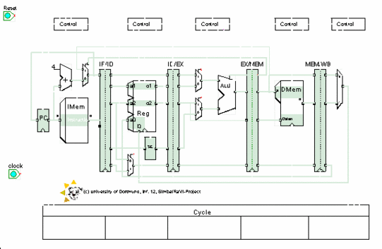
The component "pipeline1" demonstrates, how pipelining can be implemented by a hardware structure and visualizes how the instructions pass through the different pipeline stages. The component simulates the execution of instructions and shows the dynamic behaviour of the pipelined datapath. It represents a simple pipeline without the dealing of data hazards and branches.
The hardware structure specified in these components is a pipelined implementation of the MIPS (Mixed Instruction Processor Set). The implementation is widely identical to the one described in appendix A.3 of the book "Computer Architecture, A Quantitative Approach (third edition)" from Hennessy & Patterson. A schematic of the hardware structure of the component "pipeline1" is given in illustration 1. For the visualization of an unpipelined implementation of the MIPS see component "MicroProg".

The schematic of the component "pipeline1" represents the hardware structure and at the same time it defines the appearance of the visualization. At the bottom of the component you find also the table "Cycle". Each column of the table represent a pipe stage. During the visualization the active instructions will be displayed in the columns according to their current pipe stage. | ||
The content of the instruction memory unit (the current MIPS instructions), the content of the data memory unit and the content of the register file are not determined by the component. The user can change them interactively during the visualization. The instructions in the memory unit can be entered either as assembler code or as 32bit strings. The data memory values and the register values have to be entered as 32bit strings. The default instruction and data memory content and the default register file content are given in the file "imem.bin", "dmem.bin" and "reg.bin" respectively. These files are situated in the RaVi directory and will be loaded automatically during the start of the component. |
First of all it is important to mention that the hardware structure implemented in these pipeline components only includes a subset of the core MIPS instruction set. With intent to develop training components we have realised only a selected subset in order to explain the execution of MIPS instructions within a pipeline. We have not implemented a complete simulation model of the MIPS-processor.
Differing to the description of Hennessy & Patterson we have implemented an additional multiplexer in the pipe stage "Instruction Decode". The destination register field is in one of two different places depending on the instruction type. So we need a multiplexer to choose the correct portion of the IR in the MEM/WB register to specify the register destination field. The hardware structure described in the book of Hennessy & Patterson does not take this into consideration.
The lack of a zero detection unit in the pipe stage "Execution" is another difference to Hennessy & Patterson. During the execution of a branch the ALU is used for the zero test and for the jump address calculation. Consequently we will get a structure hazard and the components "pipeline1" can not execute branches correctly. Due to the fact that the components "pipeline3" and "pipeline4" deals with branches, we have decided to ignore the structure hazard here in this component.

